Construction and Build Notes
See post for Photos of Construction and Build
Introduction.Main Fuselage.Nose Section. Fin and Rudder. Canopy. Tail Cone. Wings. Building the Main Fuselage. IntroductionThis is a brief description of how I am building a large ( 1/12th scale) RC model of the Avro Vulcan B2. This is a Large Model Aircraft. See the table above for dimensions of the actual B2 and the 1/12th scale model.[Photo]
I am designing and building this model from scratch because I was unable to find a supplier of a sufficiently large kit or even suitable scale drawings for this aircraft. In designing and building this aircraft, I have attempted to achieve several objectives.
To create a design and a set of instructions which could be emailed to any intermediate builder so that he could print everything he needed from a few just a few files. Most of us can print up to A4 but very few can print anything larger, so one of my constraints was to make everything on A4 sheets. For a few diagrams I have been forced to spread the diagram over more than one sheet of A4 (they will need joining), but all of the ribs and formers for the fuselage and fin + rudder are on single sheets.
The whole construction is carried out with either 3 or 4 mm light ply, or sheet balsa ( 1.5 or 3mm. This is very close to 1/16th or 1/8th if your supplier is in the UK or USA. I have ,of course, used solid block balsa for the leading edges of the wings, elevators, ailerons, fin, rudder, nose cone and the tail cone .
One of the main difficulties encountered when designing and cutting out your own ribs from plywood is making the notches for stringers exactly the correct size and in just the right position. With this in mind, I have developed a technique which eliminates this problem and results in a stronger structure which is easier (if you don’t have pre-cut ribs) and adds only a minimal weight to the aircraft. This will be explained in detail in the relevant sections that follow.
.
Because this is a large aircraft, I have designed it to be built in several sections as follows:
.
M
ain Fuselage.This is main part of the fuselage that includes the wing roots (that part with the air intakes) and would include the four engines in the real B2.
.
Nose SectionThis is the part of the fuselage forward of the intakes, the top half of the nose section can be removed to give access to batteries and servos etc. The nose section can be removed for transportation
.
Fin and RudderThe fin and rudder are built as one piece. The fin is permanently attached to the main fuselage.
.
CanopyThe canopy is a simple small construction that is then attached to the nose section.
.
Tail ConeThis is a simple construction that attaches to the main fuselage.
.
WingsEach wing is built separately and is joined to the wing roots. The wings are easily removable for transportation.
.
Building the Main Fuselage.For the main fuselage, there are twenty four A4 sheets with ribs labelled AA through to XX. These sheets show only one half of the full rib. The other half is of course just a mirror image of the half shown. I printed just one copy of each of these sheets, I pasted them onto a sheet of card and then cut them out as accurately as I could. Then I transferred these templates (and it’s mirror image) onto a sheet of 3mm (1/8th) light plywood with both the template and the template turned over and joined as shown in the following diagram.
.

Note: It is important to keep both halves aligned. To achieve this, I drew a straight line on the plywood first and then align the base of each wing root to that line.
It is also important to make these sections are all the same width. To achieve this, I cut a sheet of light ply to the width of the sections before transferring the templates onto the ply.
10/5/08
by Vulcan12
Delete
1 – 4 of 4
If you are looking for advice and guidance for both beginners and advanced model airplane enthusiasts then you should take a look at this. This by far the most comprhensive and useful information that I have ever seen and I highly recommend it.
Model Airplanes

 1. Skeleton of the Main fuselage - without the nose and tail cone Note - this section includes the wing roots which contain the four engine nacels 22nd March 2008
 3. A Photo of the undercarriage with the removable part of the Nose Cone in the rear.
 4. The full (unsheeted) skeleton - Illustrating all of the ribs and the spars. The nose cone is complete.
  5. Sheeting has been completed on the underside and the Elevators, Ailerons and the leading edges have been constructed 16 July 2008
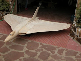


 5. Sheeting has been completed on the underside and the Elevators, Ailerons and the leading edges have been constructed 16 July 2008


.JPG)
.JPG)
